When the lights go out, the silence can be deafening – and inconvenient. A generator provides a lifeline, but without the right setup, it can be a dangerous mess. That’s where a Generator Transfer Switch Kit Installation & Wiring guide comes in. Properly installing a transfer switch isn't just about restoring power; it's about ensuring safety, protecting your valuable electronics, and complying with electrical codes.
Forget fumbling with extension cords or risking hazardous backfeeding into the utility grid. A well-installed transfer switch safely isolates your home from the grid, allowing your generator to power essential circuits without a second thought. This isn't a task for the faint of heart, but with careful planning, the right tools, and a clear understanding of each step, you can confidently navigate this critical upgrade to your home's electrical system.
At a Glance: Your Generator Transfer Switch Installation Journey
- Why You Need It: A transfer switch is essential for safely connecting a generator, preventing dangerous "backfeeding" to the utility grid and protecting appliances.
- Plan First: Meticulously list all appliances you'll power during an outage and calculate their combined wattage/amperage.
- Size Matters: Ensure your generator can handle the total load, and your transfer switch matches the amperage of your selected circuits.
- Safety Above All: Always disconnect main utility power before working on your electrical panel.
- Follow the Wires: Understand that selected home circuits will be disconnected from your main panel and re-routed to the transfer switch.
- Professional Help: If you're unsure at any point, don't hesitate to call a licensed electrician. Electricity is not a place for guesswork.
Why a Transfer Switch Isn't Just "Nice to Have"—It's Critical!
Imagine this: a storm knocks out power. You fire up your trusty portable generator, plug it into your home, and voila! Lights are back on. Sounds simple, right? Wrong. Without a transfer switch, you're creating a potentially deadly scenario known as "backfeeding."
Backfeeding occurs when your generator's power travels out of your home and into the utility lines. This can electrify power lines thought to be dead, endangering utility workers trying to restore power. It's not just illegal in most places, it's incredibly dangerous.
A transfer switch acts as a secure gatekeeper. It creates a complete physical break between your home's electrical system and the utility grid whenever your generator is engaged. This ensures power only flows one way at a time, protecting workers, your home, and your generator.
Before You Grab Your Tools: Planning & Sizing Your System
Preparation is the cornerstone of any successful electrical project. Skipping this phase can lead to an underpowered system, tripped breakers, or even equipment damage. This is where you decide what truly matters when the power goes out.
What Do You Really Need to Power? (Load Calculation)
Think about outages: what are your non-negotiables?
- Essentials: Refrigerator, freezer, well pump (if applicable), furnace fan, a few lights, perhaps a medical device.
- Comforts: TV, microwave, coffee maker, a computer.
- Luxuries: Central AC, electric oven, clothes dryer.
Walk through your home and identify the appliances on your "must-have" list. For each, find its wattage or amperage (usually on a label or in the owner's manual). - Starting Watts vs. Running Watts: Some appliances (like refrigerators or motors) have a higher "starting" wattage that lasts for a few seconds. Always account for this peak demand.
- Calculate Your Total Load: Sum the running wattage of all appliances you anticipate using simultaneously. Add the highest starting wattage of any single motor-driven appliance to this total. This gives you your total required generator capacity.
Matching Your Generator to Your Transfer Switch
Your transfer switch needs to be sized correctly for your generator and the circuits you plan to power.
- Generator Capacity: Make sure your generator’s rated output (in watts) safely exceeds your calculated total load. Overloading a generator will shorten its lifespan and could trip its internal breakers.
- Transfer Switch Amperage: Transfer switches come in various amperages (e.g., 30 amp, 50 amp). This rating dictates how much current can pass through it. The transfer switch's main breaker (or input breaker from the generator) must be rated for your generator's maximum output. Individual circuit breakers within the transfer switch will match the amperage of the household circuits you're connecting. For help selecting the right model for your home's needs, you might want to explore options to Find the right transfer switch kit.
Choosing Your Installation Spot
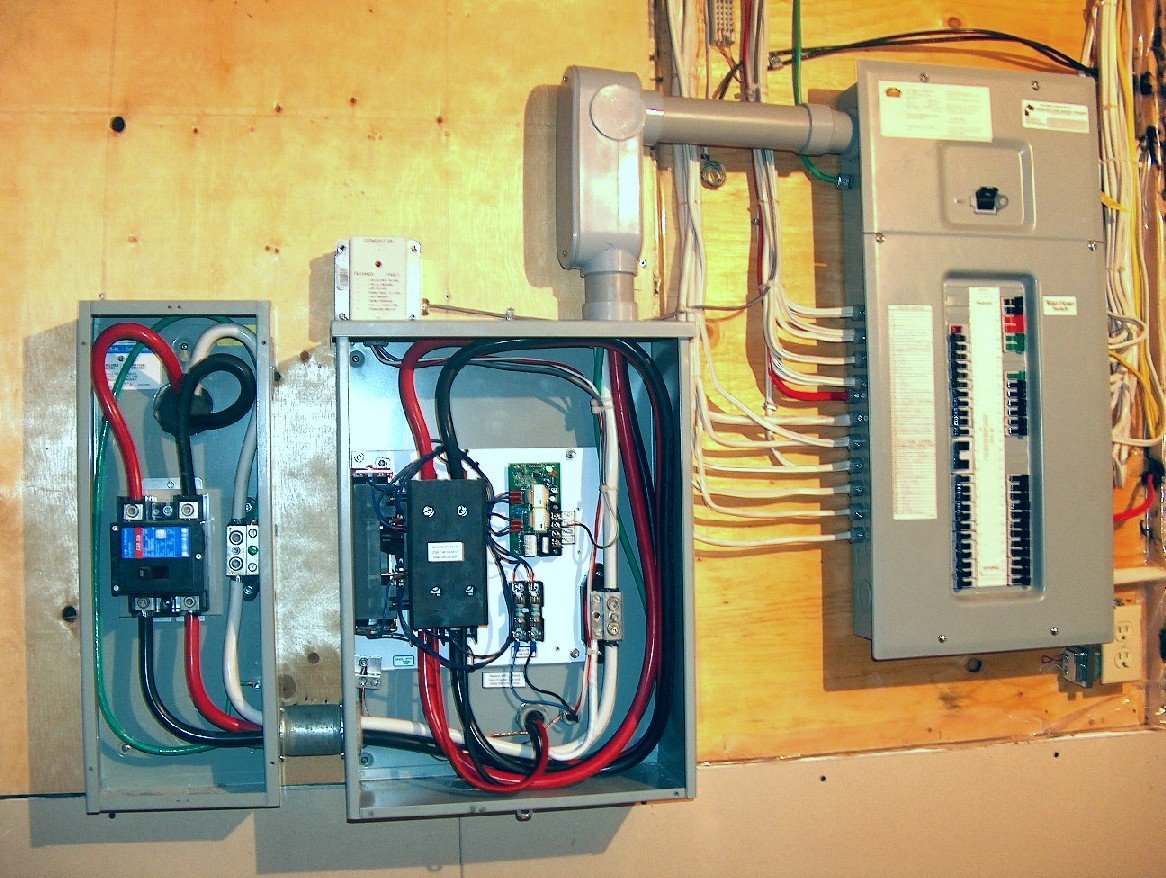
The transfer switch needs to be mounted indoors, typically next to or very near your main electrical panel.
- Proximity: Aim for about 1.5 feet (45 cm) from the midpoint of your main breaker panel. This minimizes wiring runs and keeps things tidy.
- Accessibility: Ensure it's easily accessible for operation and maintenance, but out of the way of daily traffic.
- Code Compliance: Check local electrical codes for specific clearance requirements around electrical panels.
Gather Your Arsenal: Tools & Materials You'll Need
Before you cut any power, make sure you have everything at hand. This prevents frustrating delays and ensures safety.
Tools:
- Voltage Tester/Multimeter: Absolutely critical for confirming circuits are dead.
- Screwdrivers: Phillips and flathead, various sizes.
- Wire Strippers: For safely removing insulation without damaging wires.
- Pliers: Lineman's pliers, needle-nose pliers.
- Utility Knife: For trimming conduit and insulation.
- Tape Measure: For accurate mounting.
- Level: For straight installation.
- Drill & Bits: For mounting screws and possibly knockouts.
- Conduit Benders (if using rigid conduit): For professional-looking bends.
- Marker/Labels: For clearly identifying wires and circuits.
Materials: - Generator Transfer Switch Kit: The star of the show!
- Electrical Conduit: Flexible metallic conduit (FMC) or electrical non-metallic tubing (ENT) is often used to protect wiring between the main panel and the transfer switch. Match the size to your wire bundle.
- Conduit Connectors/Fittings: Appropriate for the type of conduit you use (e.g., set-screw connectors, locknuts).
- Electrical Wire: If extending circuits, ensure it's the correct gauge for the amperage (e.g., 12-gauge for 20-amp circuits, 14-gauge for 15-amp).
- Wire Nuts/Connectors: Properly sized for the wire gauges you're joining.
- PVC Cement (if using PVC conduit): For sealing joints.
- Mounting Screws/Anchors: Appropriate for your wall material.
- Electrical Tape: For added insulation and identification.
The Installation Journey: Step-by-Step Guide to Wiring Your Transfer Switch
WARNING: Working with electricity is extremely dangerous and can cause serious injury or death. If you are not confident in your electrical skills, or if you are unfamiliar with local electrical codes, hire a licensed electrician. Always confirm power is off before touching any wires.
Phase 1: Prepping for Power Disconnect
- Safety First: Shutting Down Main Power
- Locate your home's main electrical panel (also called the service panel or breaker box).
- Identify the main breaker – usually a large double-pole breaker at the top of the panel.
- Crucially, switch this main breaker to the "OFF" position. This will cut power to your entire home.
- Verify with a voltage tester: Use your voltage tester to confirm that no power is flowing to any of the circuit breakers in the panel. Do not proceed until you've confirmed a dead panel.
- Opening Up Your Panels
- Carefully remove the front cover from your main electrical panel. Set the screws aside in a safe place.
- Remove the front cover from your new transfer switch.
Phase 2: Connecting the Transfer Switch to the Main Panel
This phase establishes the foundational wiring between your home's main power source and the transfer switch.
- Trimming and Attaching Connectors
- Measure and trim your insulating tube (conduit) to a workable length, allowing for gentle bends between the main panel and the transfer switch. Use a utility knife for flexible conduit or a pipe cutter for rigid conduit.
- Attach the appropriate conduit connectors to the ends of the conduit. For PVC, use PVC cement to secure the fittings.
- Identify one of the "knockouts" on the bottom or side of your main electrical panel and the bottom or side of your transfer switch where the conduit will enter. Remove the knockouts.
- Running the Wiring Harness
- Feed the bundle of wires from the transfer switch's wiring harness through the conduit.
- Route the conduit and wires through the prepared knockouts: one into the main electrical panel and the other into the transfer switch.
- Secure the conduit to both panels using appropriate locknuts and connectors.
- Mounting the Transfer Switch
- Position the transfer switch on the wall, approximately 1.5 feet (45 cm) from the midpoint of the main electrical panel. Use a level to ensure it's straight.
- Mark the locations for the mounting screws.
- Drill pilot holes if necessary, then securely affix the transfer switch to the wall using the provided mounting screws or appropriate hardware for your wall type.
- Connecting the Core Wires (Utility, Neutral, Ground)
- From the wiring harness coming from the main panel side, you'll have several wires.
- Incoming Utility Power: Typically, two heavy-gauge black or colored wires will feed power from your main panel to the "Utility" side of the transfer switch's main breaker. These wires connect to the two poles of the dedicated "Utility 2-pole breaker" inside the transfer switch.
- Neutral Wire: Locate the white wire in your harness. Trim approximately 5/8 inch (1.59 cm) of insulation from its end. Connect this white wire to the neutral bus bar within the transfer switch (usually a metal bar with many screws, often in the middle).
- Ground Wire: Locate the green or bare copper wire in your harness. Trim 5/8 inch (1.59 cm) of insulation. Connect this wire to the grounding bus bar in the transfer switch (a metal bar, often on the left or lower portion, sometimes bonded to the neutral bar in a main panel, but separate in a subpanel or transfer switch).
Phase 3: Integrating with Your Home's Circuits
This is where you move specific circuits from your main panel to be controlled by the transfer switch.
- Confirm Main Power is OFF: Re-verify with your voltage tester that no power is present in the main panel.
- Identify and Disconnect Appliance Wires
- Refer to your planning notes and labels. For each appliance you've selected to be generator-powered, identify its circuit breaker in the main panel.
- Carefully disconnect the "hot" (usually black or red) wire from the terminal screw on the circuit breaker for each selected appliance.
- Label each disconnected wire clearly with the appliance it controls. This is critical for correct reconnection.
- Trim and Prepare Wires
- Trim approximately 5/8 inch (1.59 cm) from the covering of each individual appliance wire you just detached.
- Connect Appliance Wires to the Transfer Switch
- One by one, route these disconnected appliance wires into the transfer switch.
- Each appliance circuit will now connect to its corresponding breaker within the transfer switch. Connect the "hot" wire from the appliance to the screw terminal on the load side of the transfer switch's dedicated breaker for that appliance.
- Ensure each wire is securely fastened to its designated terminal. Refer to the labels you created!
- Connect Transfer Switch Output Back to Main Panel (if applicable/required)
- If your transfer switch is designed to feed specific breakers back in the main panel, you'll have wires from the output side of the transfer switch's internal breakers that connect to new, dedicated breakers in your main panel. The ground truth steps imply moving the actual load wires TO the transfer switch's internal breakers, which is a common setup for smaller manual transfer switches with integrated breakers.
- Based on ground truth: The instructions suggest the individual appliance wires are directly connected to the transfer switch's internal breakers, implying these circuits are now entirely controlled by the transfer switch's breakers. The ground truth then mentions "Detach the two individual pole breakers from where each assigned appliance wire was removed." This is confusing. A common setup is to remove the load wires from the existing breakers, and then connect those load wires to new breakers within the transfer switch. I will interpret the ground truth as moving the actual load wires from the main panel's original breakers to the transfer switch's breakers.
- Neutral and Ground in Main Panel:
- Locate the white (neutral) wire(s) that were connected to the neutral bar in your main panel for the circuits you moved. Connect these white wires to the neutral bus bar in the main panel.
- Locate the green or bare copper (ground) wire(s) that were connected to the ground bar in your main panel for the circuits you moved. Connect these wires to the ground bus bar in the main panel (or the neutral bar if no separate ground bar is present and it's permitted by code for your setup).
- Re-seal and Final Checks
- Double-check all wire connections for tightness and proper insulation. Ensure no bare wires are exposed where they shouldn't be.
- Carefully replace the cover on the transfer switch.
- Carefully replace the cover on the main electrical panel.
Phase 4: The Moment of Truth (Testing Your Setup)
This is the moment of careful power restoration and system testing.
- Restore Utility Power:
- Go back to your main electrical panel and switch the main breaker back to the "ON" position.
- Check that your general household power (for circuits not connected to the transfer switch) is restored.
- Go to your transfer switch. Confirm that the circuits now connected to the transfer switch (which should be set to "Utility" mode) are receiving power from the grid.
- Switching to Generator Power:
- Following your generator's manufacturer instructions, start your generator.
- Allow the generator to warm up for a few minutes.
- Now, switch the designated circuits on your transfer switch from "Utility" to "Generator" mode.
- Observe if the selected appliances (e.g., refrigerator, lights) power on. Monitor your generator's load to ensure it's not being overloaded.
- Returning to Utility Power:
- Once you've confirmed generator operation, disconnect your generator (either by shutting it down or by disconnecting the power cord from the generator first).
- Wait a moment for the generator to spin down.
- Switch the transfer switch circuits back from "Generator" to "Utility" mode.
- Plug your generator cord back into the generator inlet (if you disconnected it) and shut down the generator according to its instructions.
Common Pitfalls to Avoid (And How to Dodge Them)
Even seasoned DIYers can make mistakes. Be mindful of these common issues:
- Under-sizing Your Generator or Transfer Switch: The most common mistake. Trying to run too many appliances on a generator that's too small will lead to tripped breakers, damaged appliances, and frustration. Dodge It: Do a thorough load calculation, and always add a buffer!
- Ignoring Local Electrical Codes: Codes exist for safety. What's acceptable in one municipality might not be in another. Dodge It: Consult your local building department or hire an electrician to ensure compliance.
- Improper Wire Connections: Loose or incorrectly terminated wires can create fire hazards, intermittent power, or system failures. Dodge It: Double-check every connection point. Give wires a gentle tug to ensure they're secure. When in doubt, call an expert.
- Forgetting to Turn Off Main Power: This is a life-threatening error. Dodge It: Treat every wire as live until you've personally verified it's dead with a voltage tester.
FAQs: Quick Answers to Your Burning Questions
Do I really need a transfer switch? Can't I just use extension cords?
For basic, temporary power to a few small appliances, extension cords can work. However, for powering hardwired appliances like furnaces, well pumps, or multiple circuits in your home, yes, you absolutely need a transfer switch. It's the only safe, code-compliant way to integrate generator power into your home's electrical system, preventing dangerous backfeeding and protecting your appliances.
Can I install a transfer switch myself?
If you have a solid understanding of basic electrical wiring, are comfortable working in your main electrical panel, and are meticulous about following instructions and safety protocols, then yes, it's possible. However, if you have any doubts or lack experience, hiring a licensed electrician is highly recommended. The risks of improper installation are severe.
What's the difference between a transfer switch and an interlock kit?
Both prevent backfeeding, but they do so differently:
- Transfer Switch: A dedicated electrical panel that physically isolates circuits from the utility and generator. It contains its own breakers for the generator-powered circuits.
- Interlock Kit: A mechanical device installed on your main electrical panel. It physically prevents the main utility breaker and the generator's inlet breaker from being "ON" simultaneously. You still use your existing main panel breakers, but the interlock ensures only one power source can feed them. Interlocks are generally less expensive but may require more manual management of individual breakers during an outage.
How often should I test my generator and transfer switch?
It's recommended to test your generator and transfer switch monthly by running the generator under a light load for 15-30 minutes. This ensures the generator starts reliably, the transfer switch functions correctly, and prevents fuel from going stale in the carburetor.
Empowering Your Emergency Preparedness
Installing a generator transfer switch kit is a significant home improvement that vastly enhances your safety and comfort during power outages. It transforms your generator from a simple backup device into a fully integrated, reliable emergency power system. While the process demands precision and respect for electrical safety, the peace of mind it delivers is immeasurable.
By understanding the "why" behind each step and diligently following this guide, you're not just installing wires and breakers—you're securing your home's resilience. Stay safe, stay powered, and enjoy the confidence that comes with being prepared.